The fourth generation of telecommunications pipes
Despite the extensiveness of the copper network, the country’s telecommunication infrastructure has many limitations in development and bandwidth. Due to the wear and tear of the existing network, the country has been incurring exorbitant costs in terms of maintenance and development for many years. Considering that the communication industry is developing all over the world, the need to replace a new generation of inactive components as a safe platform for providing urban services with wide bandwidth is more than ever the demand of employers. In this regard, Alborz Industrial Group (Alborz Pipe and Fittings Company) has included another generation of pipes under the brand name Micro Duct in its portfolio of products. This product has been completely localized with the request of engineers and employers. This product is used in the transmission of inner and outer city networks (FTTX, CCTV & IT).
Alborz Industrial Group has the ability to custom produce the size and model of Micro Duct you use.

[maxbutton id=”1″ ]
Micro duct
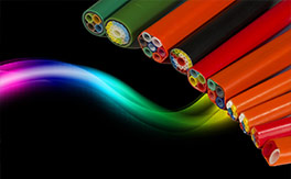
Micro-ducts are the latest and most cost-effective ways to transmit optical fiber cable (AIR BLOW), which is considered as the fourth generation of telecommunication pipes. Micro ducts are actually high density polyethylene pipes called HDPE (HIGH DENSITY POLYETHYLENE) for short. Micro ducts have a tube with a large outer diameter and several inner tubes with a smaller diameter inside the outer tube. The inner chamber of the central tube provides a path for the movement of the fiber optic cable. The use of non-degradable polyethylene materials in nature and the absence of metal structures allow direct burying of the micro-duct in the ground, thus creating an underground channel for placing optical fiber cables in the ground.
As you know, PE is one of the chemical materials that has a very high flexibility, and the production of micro ducts with polyethylene materials creates great mechanical resistance against any type of pressure, twisting, bending, and impact, and also makes it easy to bend in a screw. existing in the channel path.
In fact, micro ducts are a set of standard channels next to each other, which consists of two or more micro ducts that are placed under a cover. This product, as a new generation of transit channels for the transmission of optical fiber cables, telecommunication cameras and network transmission, which can include the number of channels and different sizes based on the way of consumption and place of implementation, also this product can be ordered in any color. be
Microducts can be produced from 1 to 12 channels and in sizes of 250-500-1000 and 2000 meters. The optical fiber cables used in the micro duct are known as AIR BLOW cables (optical fiber blowing cables or micro fiber) and these cables enter the micro duct using the AIR BLOWN FIBER (ABF) optical fiber shooting system. .
Advantages of micro duct:
- Flexibility in network design
Easy branching
The speed of network upgrade (speed of cabling operations)
Ease of network maintenance
Economical in network transmission
Minimum cost and space required for drilling and installation, especially for flat micro ducts with a width of about 3 cm.
High cable shot range
High variety in size, size and color of the product
High strength against mechanical pressure
High strength against environmental factors
Identification of network lines in long routes by color indicators
Ease of injection into the existing network in traditional telecommunication infrastructures (3- and 4-hole subducts as well as ducts in manholes)
Ability to connect to third generation O.D. pipe system (product of Alborz Industrial Group)
Reducing investment costs in projects
Up-to-date standards for micro duct cabling and branching
Variety of production in size, color, diameter and model
انواع میکرو داکت ها:


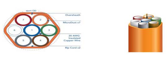


Different types of micro ducts:
- Today, micro ducts are classified according to the arrangement of micro tubes as follows:flatIn this type of micro ducts, the width of the excavation (trench) can be less than other models (up to 3 cm) and the result of this will be a significant reduction in the work and restoration of the project.
triangle
Foursquare
hexagon
Some micro duct models can be installed in old telecommunications installations including (subduct and PVC and polyethylene pipes), in this way, we specify the size of the old substrate and choose the appropriate micro duct for installation. We have developed the existing old platform several times by using micro ducts.
Production of micro duct with anti-UV materials:
Anti-UV materials can also be used in the construction of micro ducts for the purpose of protection in open warehouse environments, which can be supplied and delivered according to the order.
Micro duct production with Rip Core
A polyester thread that is placed to create a gap in the upper layer of the micro ducts (Over Sheath) and is used to strip the micro ducts.
* This option can be added or removed based on the order.
Production of micro duct with Copper Wire
The copper wire that is placed along the length of the micro-duct allows for accurate and complete identification of the route by the metal detector after the implementation of the project and the surface asphalt.
Also, if the wire is cut at a point along the route of the fiber, it is possible to identify the exact location of the break by Dynatel devices.
* This option can be added or removed based on the order.
Microduct and microtube connections
- I, Y, T, H joints
As connections are considered in the use of various types of cables and pipes and telecommunication joints, for microducts, various types of connections have been designed and produced, which are different based on their type and external diameter. The distinguishing feature of microduct joints compared to other joints is that because microducts have the ability to branch, for this reason, various joints have been designed and produced for them, which can be called I, Y, T, H joints. Which of them are defined and used for a specific task in telecommunication designs.

straight joint (I)

branching joint (Y)

branching joint (T)
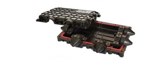
branch joint (H)
- Straight Connector
In order to connect the microduct internal tubes, there are connectors in the order, which are also different based on the size and type of the desired tube, which are called Straight Connector.
- End cap
The blocker is another microduct internal tube connection that is used to block empty tubes. By preventing the entry of dust, water and insects, this part can bring the health of the empty tubes of the micro ducts in the long term.
- Gas block
At the end of the work and after passing the fiber, gas block is used to hold the microtube and keep it stable inside the FAT.
Cables used in micro ducts (types of micro fibers):
Air-Blowing cables or macro fiber can be used to be placed inside the micro duct. Despite the reduction in size compared to ground and channel cables, the data transmission capacity of Micro cables is equal to the mentioned cables. These cables are used in all communication and telecommunication projects due to their physical characteristics and the ability to be placed inside the microduct. A special type of this category has anti-robust properties. Micro cables are also used in fiber to the home (FTTH) projects in the field of access.
These products are classified in several different categories:
Microfiber has several loose tubes, or in other words, multitube: in this category, each loose tube contains 12 cores of 24 cores, and each optical fiber microcable has between 12 and 288 cores.
Microfiber is a loose tube called Central Tube: this type of micro cable includes 2 to 24 cores.
Fiber optic micro duct and micro cable
Micro fiber optic cable and microduct is a term applied to a new model of fiber optic cables used in FTTH projects or bringing fiber to homes, which are cables with high capacity and small diameter. Bend Insensitive or BI fibers allow optical fibers to be placed inside microducts with a much higher density because BI fibers are less sensitive to bending compared to conventional fiber optic fibers.
BI fibers can be covered with primary buffer coatings with a smaller diameter, 200 microns or less, than the 250 microns that is typical for normal fiber strands, which allows more fibers to be compacted in less space. be given
Necessary points when using micro duct
For pipes whose diameter is less than 5 cm, the bending radius must be at least 20 times the diameter of the micro tube, and for pipes above 5 cm, the bending radius must be 20 times the inner diameter.
In the highest capacity, a maximum of 50% in ideal conditions and 70% of the final capacity of the micro ducts should be used (filled). By changing this number from 50% to 70%, the length of the integrated shot of microfiber decreases.
When directing the duct to the outside, it is necessary to have a branching joint.

Optical fiber cabling using a cable shot device (Air-Blown Fiber)
Optical fiber shooting operation is a very precise and specialized process in which by creating air pressure by strong compressors and with a Micro Fiber Blower device, they shoot the fiber inside the microduct and perform micro fiber cabling for distances of more than 1 km.
It is very important that the equipment used in the optical fiber shooting device supports the size of the optical fiber cable, otherwise the cable in the so-called shooting device will buckle and slip and the efficiency of micro fiber shooting will decrease. Also, the quality of the micro ducts used is effective in the way fiber optic shooting works.
In this technology, air is used as a tool to reduce friction between the body of the microfiber cable and the inner wall of the micro duct. There are two types of friction that must be overcome in order to shoot optical fiber in ducts
Static friction
It is the force that does not exist between the contact surfaces when an object moves, which tells us how much force we need to move that object forward.
dynamic friction
Dynamic friction is the force that exists when an object moves between contact surfaces. By calculating this friction, we can know how much force is required to hold the fiber and prevent contact with the body of the microduct.
The heavier the object, the greater the friction. Therefore, the higher the number of cores in the available microfiber cable, the more force and air will be required to overcome the friction. Lubricants such as air can be used to reduce friction between two surfaces. With a lubricant, the frictional resistance is almost independent of the force between the two surfaces and does not depend much on the material of the surfaces.
When designing and laying optical fiber, you should have a glimpse of the future and predict minimums. Issues such as the type of fiber and the number of its “cores” should also be considered (Cores), so that a few additional cores should also be considered so that in case of damage during installation or during work, it can act as a replacement. What systems will be installed in the future and how many cores will be needed and whether there is a way to change the type of these cores should be considered.
Differences in the implementation of old and new systems:


Use of micro duct to make buildings smart
In order to make smart in modern and up-to-date buildings, the microduct substrate can be used in the building, which removes a significant amount of copper cables (network cable, coaxial or antenna cable, iPhone cable, etc.) Nouri moved towards a smart building, and if microducts are used in the floor of the units, the security and health of the fibers can be guaranteed. The points of using microducts inside the units are as follows
There should not be more than two 90 degree curves or one 180 degree curve in the micro duct path. If there is, a design should be such that Pull Box is used.
For pipes with a diameter less than 5 cm, the minimum bending radius is 6 times the inner diameter, and for pipes above 5 cm, the bending radius is 10 times the inner diameter.
It is not acceptable to screw up on the route.
If the air blown system is not used, the amount of tensile force of the cable is directly related to the performance of the micro duct elements such as the length of the pipe, the type of coating, the number of bends, etc. Therefore, the design of the micro duct network should not be such that the tensile force does not occur. G from the nominal capacity Fiber will be increased (tensile force can be reduced by using psychostimulants)
Preferably, a straight path should be seen in the design of the Pull Box (avoid installation and design in places with even mild arches)
When the microducts reach a gathering point, they should be placed 2.5 to 7.5 cm above the floor level of the room. And this action causes liquids not to penetrate into the duct during construction and concrete pouring and does not lead to the pipe being seized.
All empty microducts should be blocked with an end cap
The number of route branches should be based on the order to the microduct manufacturer.
Concreting on the routes can be one-stage or two-stage.
لیست پروژه های انجام شده میکرو داکت
| ردیف |
نام پروژه |
نوع میکروداکت |
سال |
| 1 |
Chaharmahal and Bakhtiari municipality |
7 channels |
1395 |
| 2 |
Technology and Information Organization of Karaj Municipality |
7 channels |
1395 |
| 3 |
fanap |
7 channels |
1395 |
| 4 |
Fars Province Telecommunication Company |
7 channels |
1395 |
| 5 |
Industrial town of Isfahan |
7 channels |
1396 |
| 6 |
Saba Net (residential settlement in Bushehr) |
4 channels |
1396 |
| 7 |
Gilan Industrial Town |
7 channels |
1396 |
|
4 channels |




نقد و بررسیها
هیچ دیدگاهی برای این محصول نوشته نشده است.