
Alborz Industrial Group, backed by more than five decades of specialized experience in the design and production of polymer and industrial products in the fields of electricity, telecommunications, and networking, has achieved a distinguished position in infrastructure industries, particularly in the country’s telecommunication sector, and has always been among the pioneers of new telecommunication technologies in Iran.
Today, by expanding its scope of activities, Alborz Industrial Group, in addition to its presence as a manufacturer in the telecommunications industry, has entered the field of executing complete FTTH (Fiber to the Home) projects. The company has so far participated in numerous projects across the country as a direct contractor or EPC supplier. These projects include the full range of activities from network design, equipment supply, mechanized trenching, ODC and FAT installation, fiber shooting, fusion splicing, and OTDR testing, all carried out with the support of experienced personnel and modern equipment.
By leveraging domestic production capabilities, engineering knowledge, and practical experience, Alborz Industrial Group is ready to provide comprehensive FTTH services on urban, industrial, and commercial scales for organizations, operators, and infrastructure entities.
At this stage, a precise survey of the project area is carried out, and the fiber optic network structure is designed in accordance with FTTH standards. This stage includes determining fiber routes, equipment installation locations (such as FAT, OLT, ODF), and connection points.
Details of Actions:
1-1 Field Survey:
The design team visits the project site and examines the physical conditions:
Type of route (soil, asphalt, roadway, sidewalk)
Existing obstacles such as drainage channels, water and gas pipelines, other urban utilities, and subscriber buildings
1-2 Preparation of Initial Network Map:
Based on field data, the route trench map, FAT box positioning, joint points, and microduct paths are prepared.
Common Tools: AutoCAD, GIS, or specialized FTTH design tools
1-3 Capacity Calculations:
Based on the number of subscribers and distances, splitter capacity (1:8, 1:16, etc.), number of microducts, type of fiber, and other parameters are determined.
1-4 Final Executive Map (As-Built Plan):
The final detailed design is prepared along with an execution plan for the implementation team.
Before starting execution, all necessary permits must be obtained from the relevant authorities. This step is a vital prerequisite to prevent the project from being halted during implementation and involves coordination with the municipality, utility companies, traffic police, and other related institutions.
Details of Actions:
2-1 Correspondence and Obtaining Excavation Permits:
Submitting the designed maps to the municipality, telecommunication authorities, or other relevant organizations
Following up to obtain permits for excavation in public roads, sidewalks, or dedicated routes
In some cases, coordination with traffic police is required to manage traffic in busy streets
2-2 Route Marking for Excavation:
Before machinery enters the site, the excavation route is marked on the ground with spray paint or physical markers.
2-3 Coordination with Private Owners or Special Premises:
In certain cases, passing through private property or specific sites (such as parking lots, commercial centers, etc.) requires written consent.
2-4 Procurement of Materials and Logistics Preparation:
Providing microducts, manholes, FATs, and other required components, and transporting equipment such as trenchers, cable trailers, generators, etc.
2-5 Preparation of the Execution Team and Task Assignment
At this stage, the project execution begins. Mechanized trenching is carried out using a trencher, and microducts are placed simultaneously in the prepared bed. ODC cabinets and FAT distribution boxes are also installed in designated points according to the execution plan. Proper installation practices have a direct impact on the performance and stability of the FTTH network.
Details of Actions:
3-1 Trenching with Trencher:
The trencher performs excavation at the standard depth (typically around 40–60 cm).
In locations where machinery cannot operate (such as intersections, narrow alleys, curbs), excavation is performed manually.
3-2 Canal Bed Preparation:
After excavation, the bottom of the trench is covered with about 5 cm of soft magnesium sand to prevent damage to the microducts.
3-3 Microduct Installation:
Microducts are placed in the prepared bed. After installation, an additional layer of soft sand is poured on top to fully secure them in a safe bed.
On top of the sand, a warning tape is installed so that the ducts can be identified during any future excavation.
3-4 Microduct Connection:
For extending duct routes, I-joints and straight connectors are used.
At branching points toward FATs, T- or H-type joints are used depending on the route shape to properly distribute the microducts.
3-5 Manhole and Handhole Installation:
At appropriate intervals or splice (fusion) points, manholes or access boxes are installed.
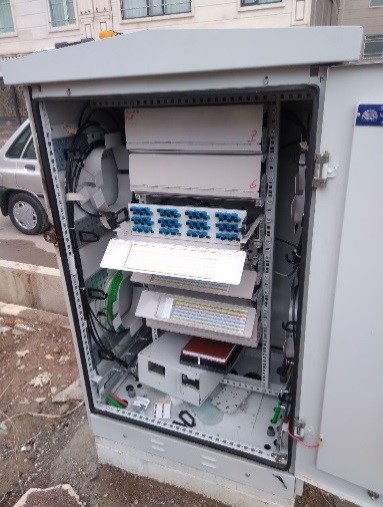
3-6 ODC (Optical Distribution Cabinet) Installation:
Before FAT installation, ODC cabinets are installed at designated sidewalk locations. These cabinets act as fiber distribution points to the FATs.
ODCs are installed on standard concrete foundations and connected to the central office and OLT through the main microducts.
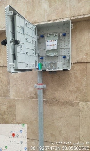
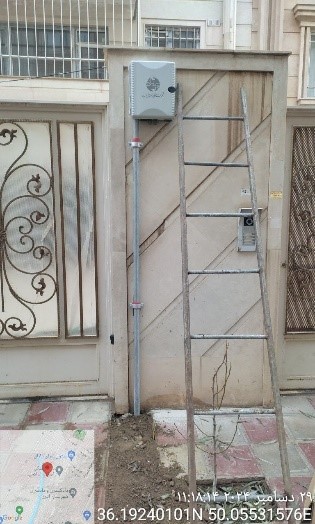
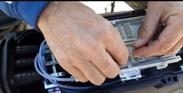
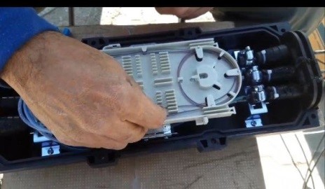
3-7 FAT (Fiber Access Terminal) Installation:
FAT boxes are installed at designated positions on building walls or galvanized poles using proper clamps. These boxes serve as the final fiber distribution point to subscribers.
3-8 Canal Backfilling and Route Restoration:
After microduct placement, the trench is backfilled with soft soil or sand.
Finally, the trench is restored with construction materials, concrete, and asphalt.
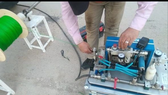
After preparing the duct bed and installing the microducts, the next step is transferring (jetting or blowing) the microfibers inside the microducts. This operation is carried out in a controlled manner using specialized machines. At this stage, the quality of the duct path and the accuracy of the previous work have a direct impact on the success of the operation.
Details of Actions:
4-1 Route Preparation:
First, the duct path is checked to ensure its integrity. The duct is tested using compressed air. In case of blockage or sharp bends, route correction or reconstruction is performed.
4-2 Microfiber Jetting (Blowing):
Air-blowing machines are used to jet microfibers. The microfibers are carefully unwound from the reel and injected into the microduct from start to end. Air pressure and speed are adjusted according to the duct length and diameter.
4-3 Control and Marking:
After jetting is completed, the injected fibers are marked (numbering at both ends of the route) to prevent errors in the next stages. All information related to each fiber (number, route, length) is documented.
4-4 Preparation for Splicing (Fusion):
Fibers entering the FAT or ODF are arranged and prepared for fusion splicing. Extra length is considered in each box or joint location to allow proper fusion.
Key Execution Notes:
Before jetting, microducts must be completely dry and free of obstacles.
Avoid looping or excessive pulling of fibers.
If required, special gels are used to reduce friction.
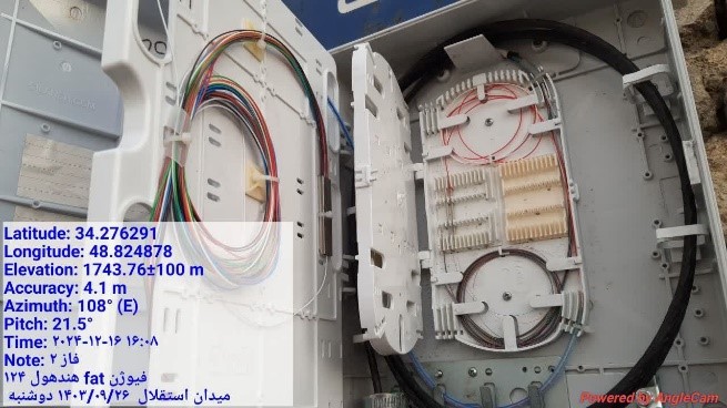
At this stage, the jetted fibers are connected at the endpoints (such as FAT and ODF). The splicing is carried out using a fusion splicer. Then, OTDR testing is performed to verify the quality and integrity of the connections, preparing the network for final operation.
Details of Actions:
5-1 Preparation for Fusion Splicing:
Fibers at each connection point (FDB, FAT, or ODF) are arranged and stripped to the proper length. Using a stripper, the fiber coating is removed, and the fibers are cleaned and prepared for splicing. Before fusion, each fiber is cut with a cleaver to ensure a perfectly flat end.
5-2 Fusion Splicing Operation:
Fibers are precisely and permanently joined using a fusion splicer. The splice point is placed in a dedicated cassette and insulated with a heat-shrink sleeve or fusion protector. Fiber arrangement inside the cassette must follow the design to avoid confusion during future troubleshooting.
5-3 Network Testing with OTDR:
OTDR testing is performed to evaluate the precise performance of the network.
This test helps identify:
Loss at each splice point
Exact location of each fusion splice or joint
Presence of breaks or attenuation along the fiber route
The test results are recorded and stored as part of the project documentation.
5-4 Completion of Documentation and Project Handover:
The final report includes:
As-Built drawings
Fiber and route lists
OTDR test results
Execution photos and equipment installation locations
The project is then prepared for delivery to the client.
Summary:
Implementing FTTH projects through mechanized methods and modern equipment not only accelerates execution but also ensures the quality and stability of the network. With reliance on its expert team, global standards, and operational experience, our company is fully prepared to implement FTTH projects at various scales.
In this report, we review the complete process of executing an FTTH (Fiber to the Home) project, step by step, from design to testing and final delivery. The project has been carried out using microduct technology and mechanized trenching with a trencher, and includes FAT installation, fiber blowing, fusion splicing, and OTDR testing.
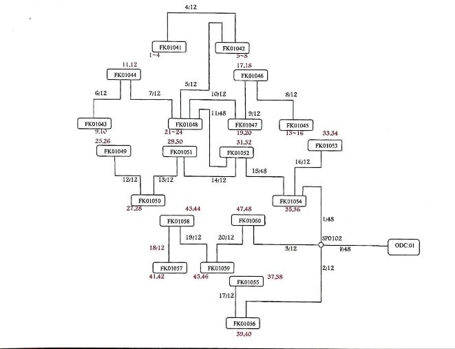
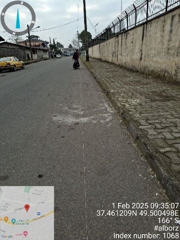
Step 1: Network Design
In the first stage, the technical team conducts a site survey to determine fiber optic routes, equipment placement (FAT, ODF, manholes, etc.), and subscriber capacity requirements. Based on this data, a precise execution plan (network design map) is prepared.
(Insert image of network design or site survey here)
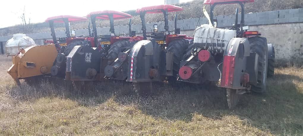
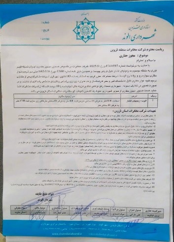
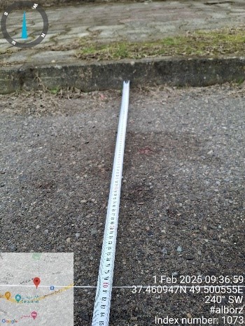
Step 2: Permits and Equipment Preparation
After preparing the final design, all necessary permits are obtained from the municipality, telecommunication authorities, and other relevant institutions. At the same time, the required materials and equipment, including microducts, manholes, FATs, and accessories, are supplied.
(Insert image of excavation permit, prepared equipment, or marked route here)
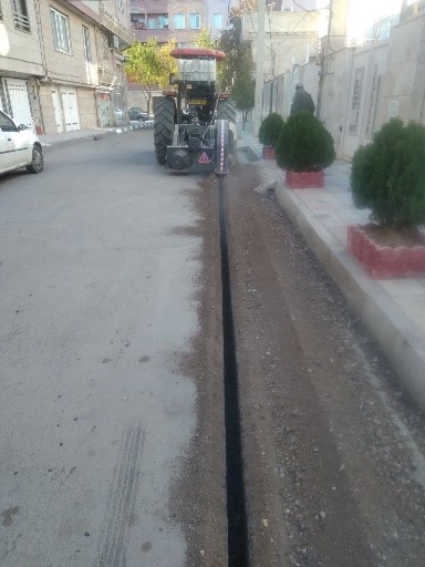
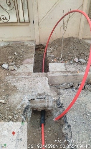
Step 3: Trenching, Microduct, and FAT Installation
The trenching process is carried out using a trencher machine. The bottom of the trench is covered with a 5 cm layer of soft magnesium sand. Microducts are then placed in the bed, covered with another sand layer, and protected with a warning tape.
At branching points, I, T, and H joints are used, while straight connectors are applied for duct extensions. FATs are installed at specified locations according to the design plan.
(Insert images of trenching, duct placement, warning tape, and FAT installation here)
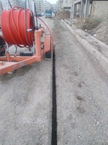
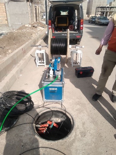
Step 4: Microfiber Blowing and Preparation for Splicing
After preparing the routes, fiber optic cables are blown into the microducts using air-blowing machines. The routes are tested, and fibers are marked and organized at the endpoints (FAT and ODF) to be ready for fusion splicing.
(Insert image of fiber blowing machine, fiber reels, and marking process here)
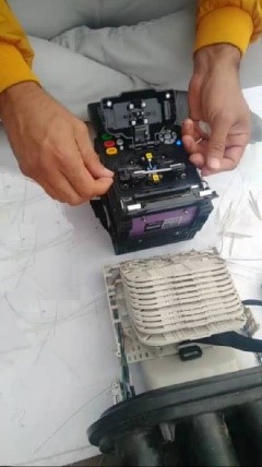
Step 5: Fusion Splicing, OTDR Testing, and Project Delivery
In this final stage, fibers are precisely spliced using a fusion splicer. Then, OTDR testing is performed to evaluate splice quality and fiber route integrity. Finally, all project documentation, including As-Built drawings, route lists, and test results, is prepared and delivered to the client.
Contact Infromation
Tehran, 18th km of Fath Highway, Tiba Industrial Complex, Negarestan Street, No. 98
Phone Number : 02146079801 – 0214749
All material and intellectual rights of this website belong to Alborz Industrial Group.