Executive Instruction for Ducting and Installation of C.O.D Pipes:
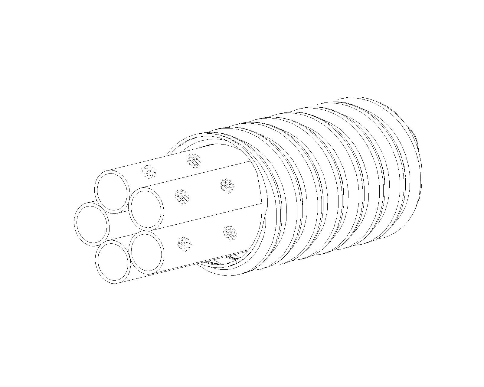
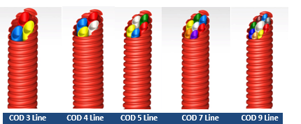
Polyethylene Corrugated Duct with Subduct (PE Corrugated Optical Ducts)
Definition of Ducting:
The operation that results in the construction of a duct and the installation of COD pipes with the relevant conditions and specifications for the passage, protection, and optimization of the transmission network is called ducting.
Review of the Drawing and Its Implementation at the Project Site:
Before any excavation work, based on the prepared execution details, the initial required information regarding other underground utilities along the excavation route in the mentioned area must be collected, and after review and the necessary requirements, the route marking (staking) shall be carried out.
Method for Calculating Excavation Depth / Bottom Width, Top Width, and Bedding Slope of the Duct:
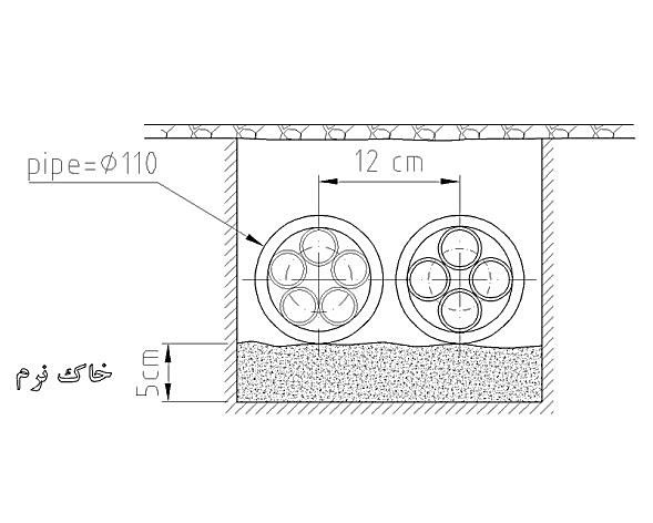
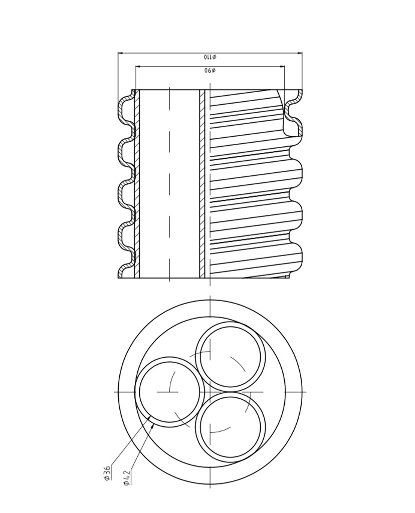
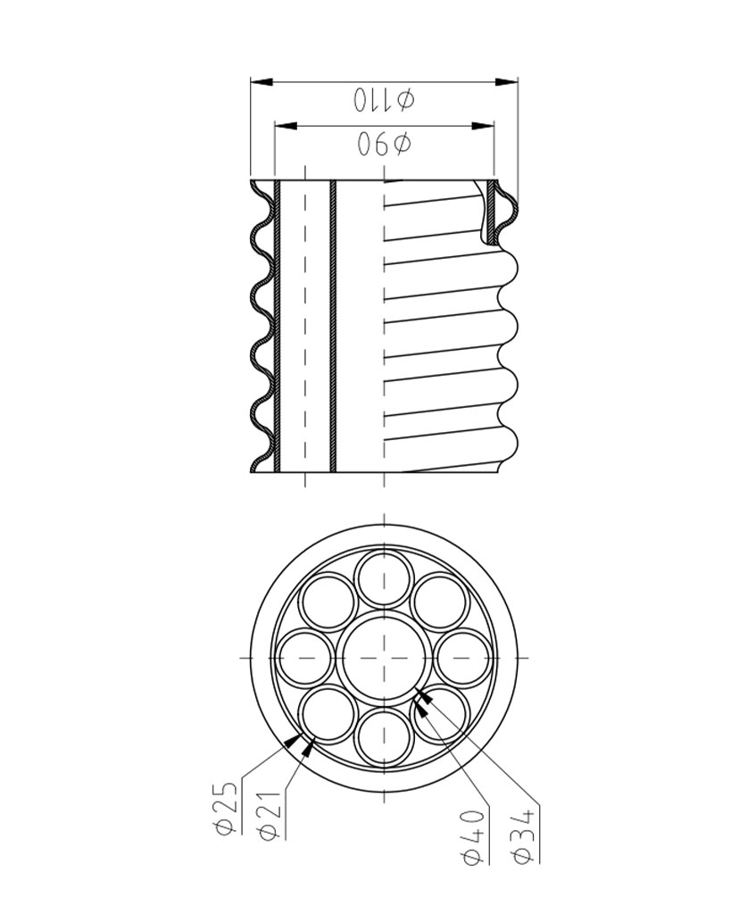
If (N) is the number of ducts (the mentioned pipes) in one horizontal row, the bottom width of the duct for excavation is obtained from the following relation:
If we consider 11 centimeters as the distance between the centers of two mentioned pipes. (according to Figure 1)
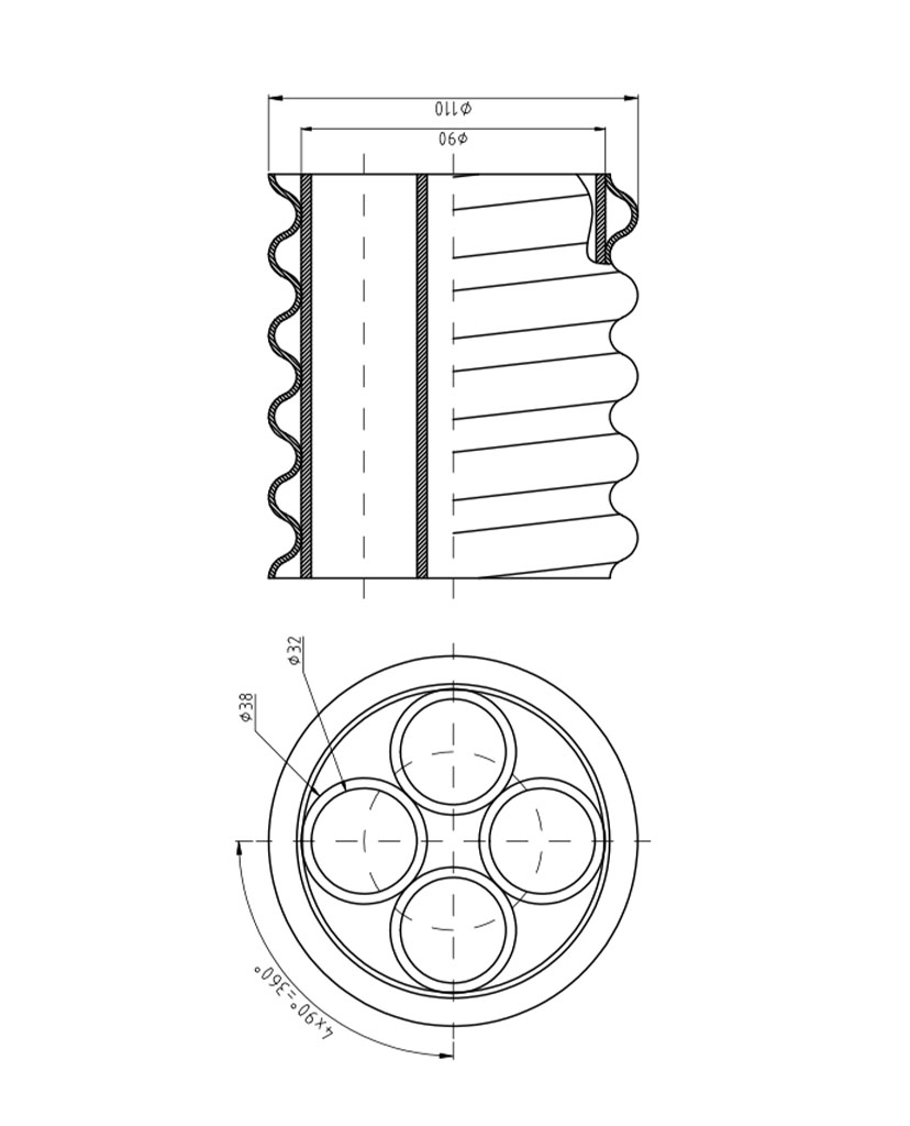
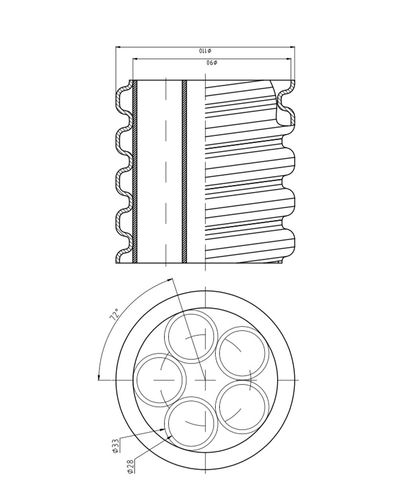
- If M is the number of vertical ducts in the channel, the excavation depth is obtained from the following relation. (according to Figures 2 and 3)
70 cm + 12 cm (M-1) = Excavation depth (carriageway)
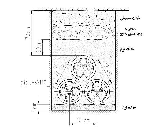
40 cm + 12 cm (M-1) = Excavation depth (sidewalk)
- If we denote the excavation depth by h, the top width is obtained from the following relation:
1/5 * h + bottom width = top width
Note: The values 70 and 40 are constant and are calculated respectively as the distance of the highest duct (the mentioned pipe) in the channel from the ground surface in the execution of the carriageway or sidewalk.
The excavation depth may change depending on the type of pipe used and its flexibility along the route when encountering obstacles.
Observance of Safety Points Before Execution:
Starting execution operations after coordination with the municipality and other urban service organizations, while observing all safety items such as the following, is mandatory:
- Installation of protective fencing
- Installation of warning signs (flashing lights, safety signs, white reflective boards, and other warning signs)
- Personal protective equipment (shoes, helmet, goggles, gloves, boots, etc.)
Excavation and Earthwork:
Excavation and earthwork, depending on the height of underground obstacles and ground hardness, can be done in two ways.
a) Semi-automatic b) Automatic
Excavation and earthwork with a semi-automatic machine: After route marking (lining) of the ducting path, asphalt cutting is carried out with an asphalt cutter.
Earthwork in hard ground:
In such cases, it is necessary to use a compressor with the required number of hammers or a jackhammer, considering the trench width and depth. In excavating such grounds, it is not necessary to create a wall slope.
Earthwork in semi-hard and loose ground:
In such grounds, considering the excavation depth and obstacles ahead, a trencher with asphalt cutting and earthwork capability may be used, or traditional tools such as (shovel, pickaxe) or an excavator.
Note: In case of possible soil collapse during excavation (especially at depths greater than 60 centimeters), boards connected to the duct walls and, as far as possible, extending to the full depth of the duct must be used. To brace the duct walls, jacks or iron rods with T-shaped struts must be employed.
Encounter of the Duct Route with Obstacles:
Considering the flexibility and integrity of the mentioned pipes (COD), when the duct route encounters obstacles, two situations can be used:
a) Encounter at an intersection:
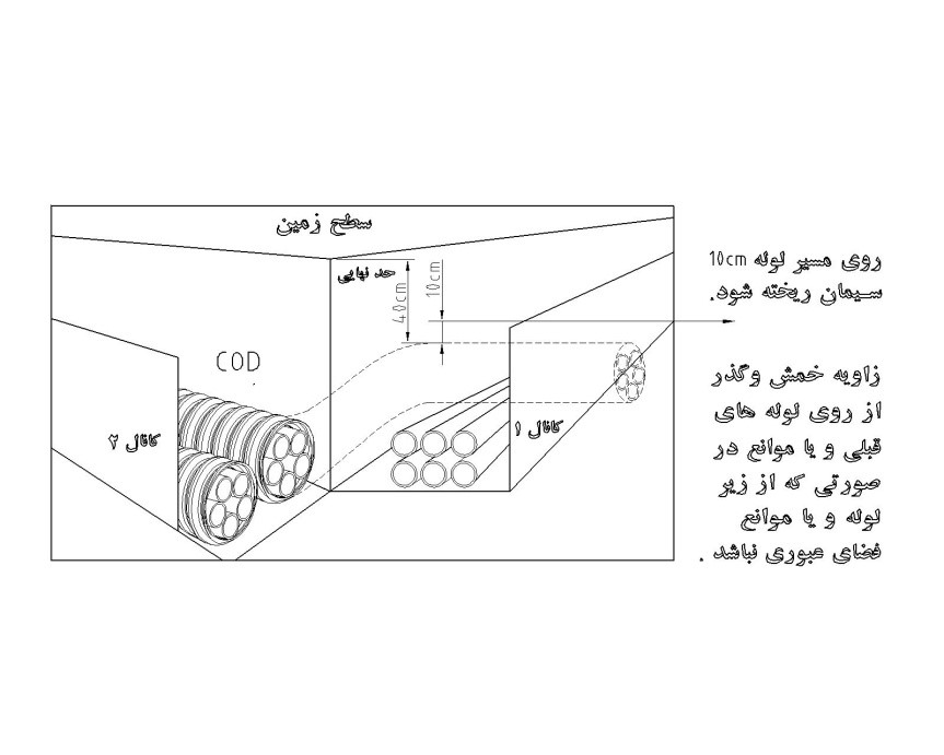
Given the flexibility of the mentioned polyethylene subducted COD pipes and their integral production, while maintaining the permissible excavation height and the height of the last pipe from the ground surface, if it is not possible to pass under the obstacles, move toward the surface and pour concrete with a height of 10 centimeters over it. (according to Figure 4)
b) Parallel crossing:
Routing the duct in parallel conditions is permitted with a one-meter clearance from main water pipes (trunk line) / gas / 64 kV high-voltage power cables, and the permissible clearance for sewage pipes and 20 kV power cables is half a meter; and if, in the aforementioned cases, observing the stated clearances is not possible, the method and type of execution will be determined on a case-by-case basis through review and expert assessment.
Method of Transporting / Storing Polyethylene Subducted COD Pipes:
- COD pipes supplied as 250-meter coils must be stored under normal weather conditions away from direct sunlight. (covered places)
- COD coils must be loaded, transported, and stored in an upright position.
- In sub-zero weather conditions, sufficient care must be taken during loading, transport, and storage.
- All fittings and accessories for COD pipes, as described below, must be preserved and stored in the warehouse under standard warehousing conditions.
Relevant accessories:
Note: The necessary forecasting and facilities to prevent possible hazards in the warehouse or at the product storage site are mandatory and essential.
Preparing the Duct Bed:
After leveling the duct bed (removing large and sharp stones), the entire duct must be covered with soft soil to a height of 5 cm. (soft, sieved soil collected on-site without debris and large, sharp stones may be used in the project)
Arrangement and Permissible Bending of Polyethylene Subducted COD Pipes:
- Excavation of the duct when connecting the pipe to a 100 × 100 × 100 inspection chamber:
The duct must be excavated so that the distance between the last pipe and the adjacent wall of the duct is at least 5 centimeters. The duct depth must be such that after placing the last pipe, the distance of the last terminator along the route to the sidewalk asphalt surface is 40 centimeters and in the carriageway is 70 centimeters.
- Excavation of the duct when connecting the pipe to a Type 2 manhole:
The duct must be excavated so that the distance between the last pipe and the adjacent wall of the duct is at least 5 centimeters. The duct depth must be such that after placing the last pipe, the distance of the last terminator along the route to the asphalt surface in the sidewalk is 100 centimeters and in the carriageway is 120 centimeters.
- For arranging the mentioned (COD) pipes, there is no need to use bottom and middle combs.
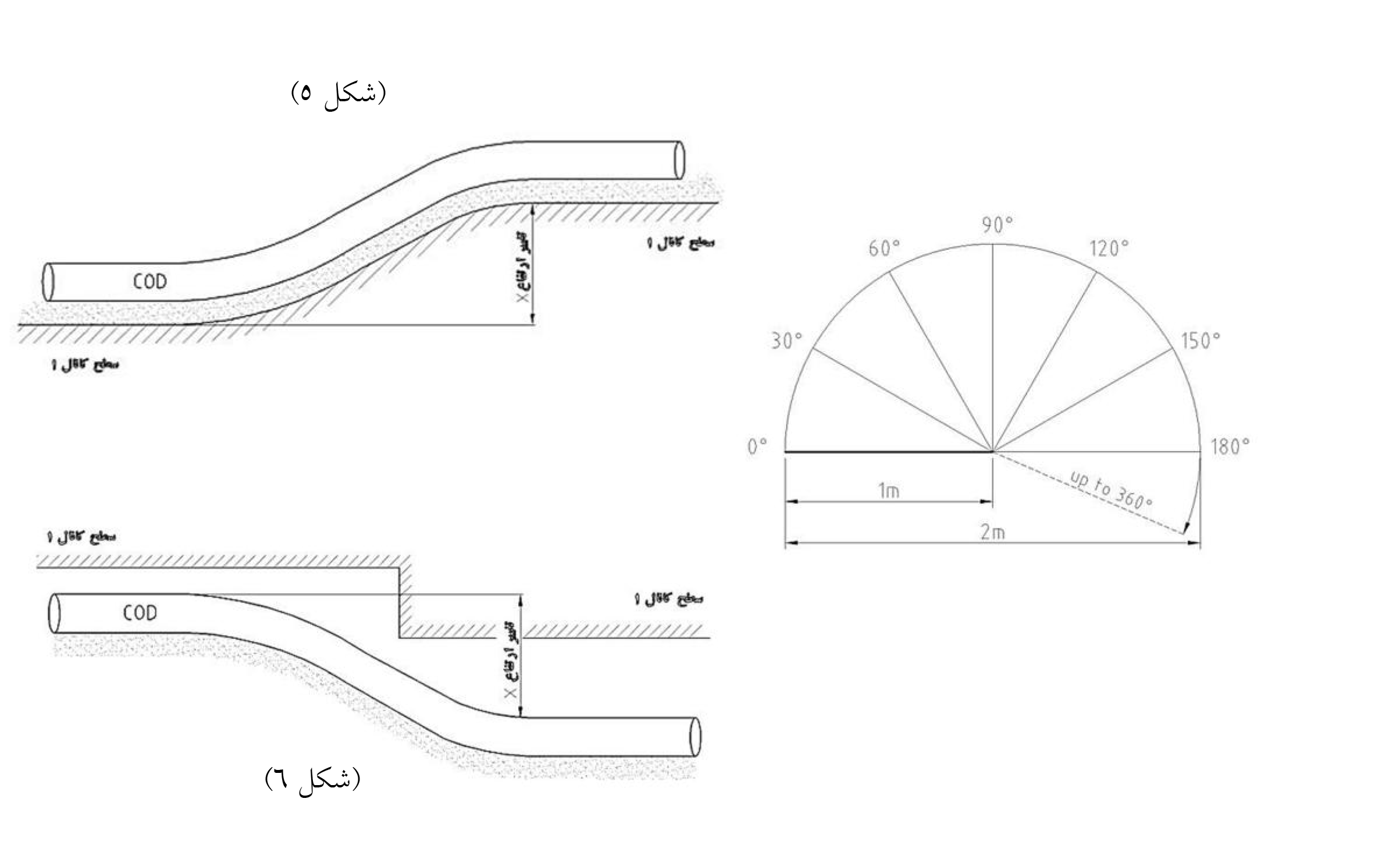
- Given the flexibility and strength of polyethylene subducted COD pipes with a bending angle capability to a radius of one meter and forming a 360-degree arc, the absence of geometric changes of the pipe under variable conditions in ducts is considered an advantage. (Figures 5 and 6)
Observing Manhole Spacing in Design Based on Pipe Bending, along with the COD Pipe Bending Table:
Since the manhole construction part in the transmission network entails significant costs, using 250-meter coils of polyethylene subducted COD pipes and a pipe joint can increase the distance between manholes from 250 meters to 500 meters, or even up to 1000 meters. As the mentioned pipes are produced in 250-meter coils and have very suitable flexibility and mechanical strength, they can be used at various angles and route changes in design.
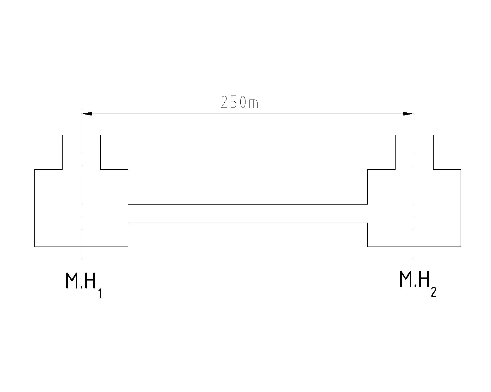
a) Duct route length from the center of Manhole (1) to the center of Manhole (2) based on 250 meters in length.
(According to Figure 7)
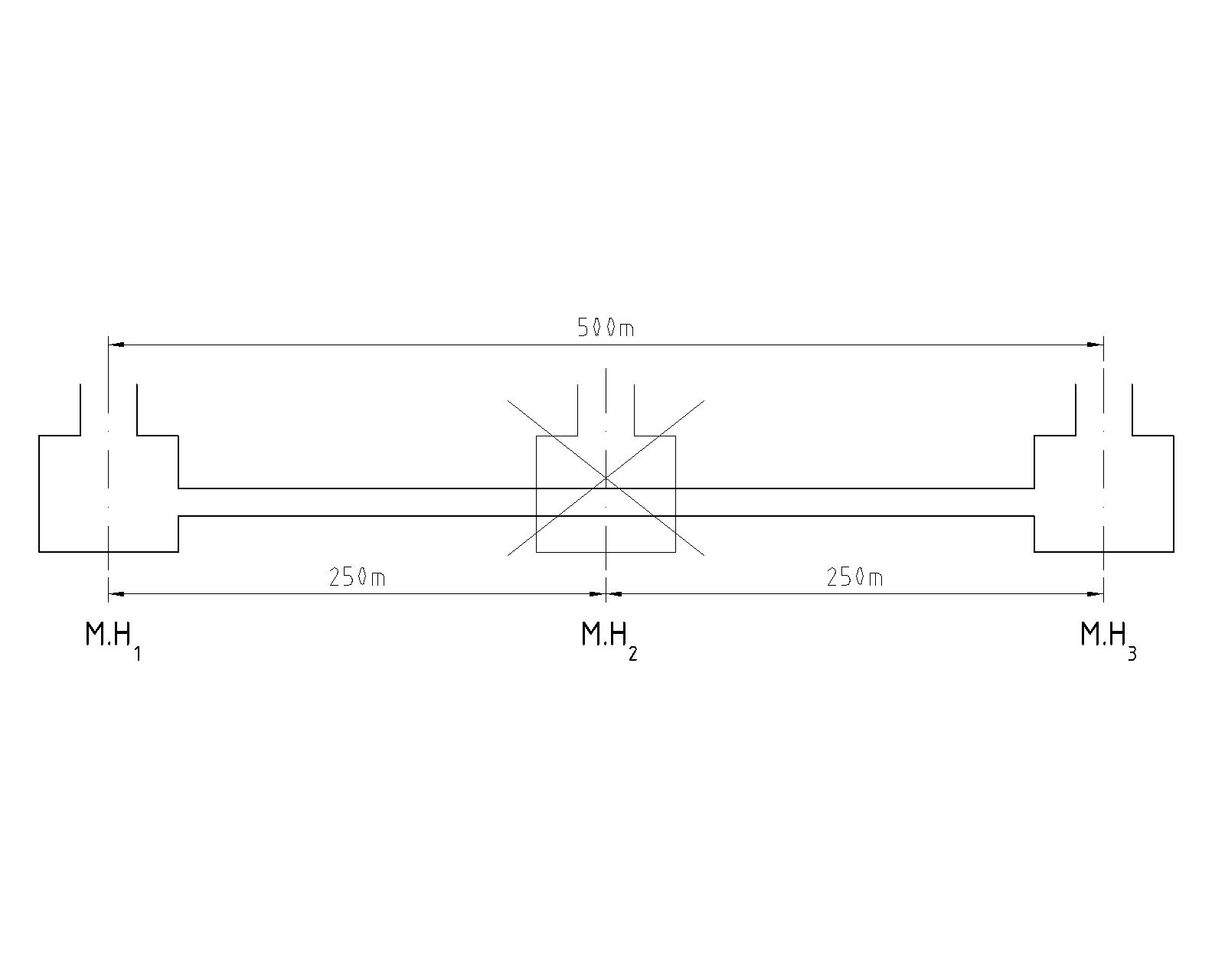
b) Duct route length from the center of Manhole (1) to the center of Manhole (3) with a distance of 500 meters, by eliminating Manhole (2) and replacing it with a (COD) pipe joint: (According to Figure 8)
c) A bent duct route and/or repeated bends and/or bends with different angles:
- Bent duct route: (Figure 9)
- Repeated bends: (according to Figures 10 / 11 / 12)
Bending Radius Determination Table:
How to Select COD Pipe Length between 100×100×100 Inspection Chambers or Type 2 Manholes:
To estimate the pipe length between two 100×100×100 inspection chambers or a Type 2 manhole, based on the dimensions of the manhole and considering the length of the entry joint into the manhole (connector) and the thickness of its concrete wall, for installation to 100×100×100 inspection chambers at a 500-meter spacing, the pipe length should be calculated as 502 meters; and for installation to Type 2 manholes at a 500-meter spacing, the pipe length should be calculated as 505 meters.
Method of Laying Polyethylene Subducted COD Pipes in the Duct:
Pipe laying method:
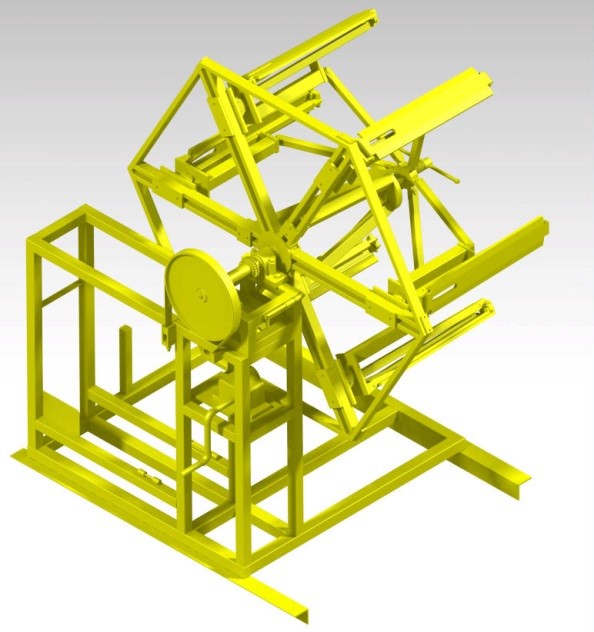
- After excavation and leveling the duct bed with soft soil to a height of 5 centimeters. The polyethylene subducted pipes, produced in 250-meter coils, are mounted on the rewinder (coil opener).
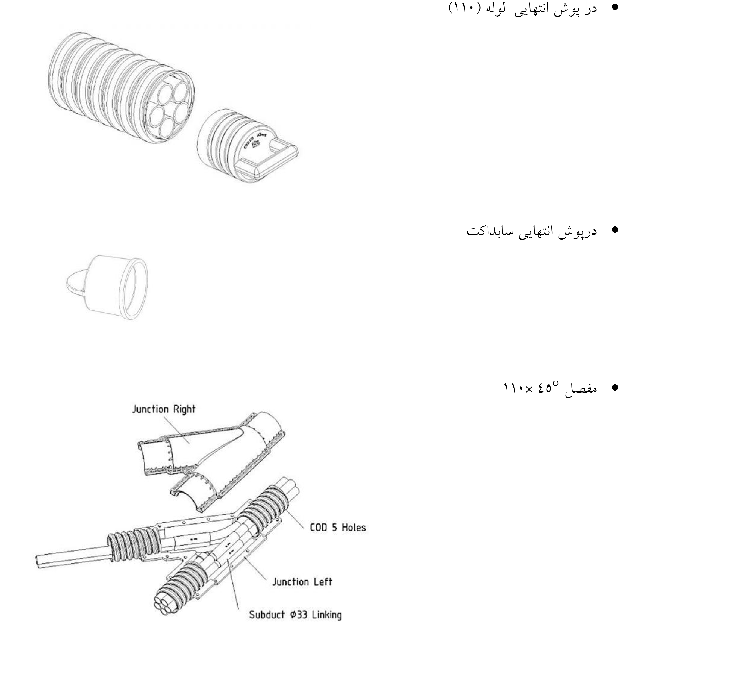
- The 110 end cap will be installed on the COD pipes and they will be ready to be opened by the rewinder.

- The mentioned pipe enters the duct mouth and is prepared to connect to the winch. The winch’s job is to pull the pipe into the duct.
- The winch is fixed at the other end of the duct, and its pulling cable is routed through all possible obstacles (transverse crossing cables / transverse crossing water and gas pipes and bridges) across the duct crossing and connected to the pipe entering the duct. The winch is then operated and guides the pipe inside the duct. (from the entrance of Manhole No. 1 toward Manhole No. 2)
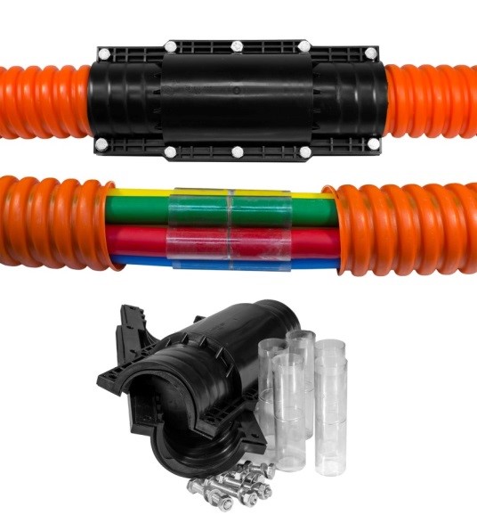
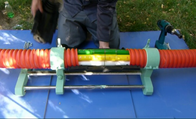
How to Connect Two 250-Meter Coils of COD Pipe to Each Other at a 500-Meter Distance:
- First, the 110 end caps of both pipes inserted into the duct are removed.
- The corrugated cover (COD pipe cover) of both pipes is removed with a cutter.
- The connection point (fusion) of the inner subducts and the corrugated cover (COD pipe cover) is cleaned with a file and prepared for installing the glass sleeves that connect the two pipes.
- Using a jig tool, the two main pipes are brought close together so that the colored subducts of both pipes are connected and engaged with each other according to the color coding by the glass sleeve until they reach the reference mark.
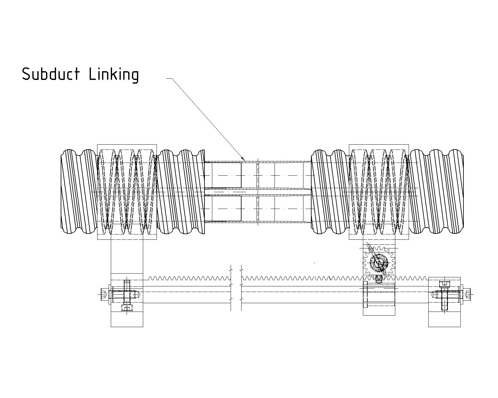
5. The colored subducts of the pipe must all be cut to the same length and be free of any sharp edges and burrs. (for seating in the glass sleeve)
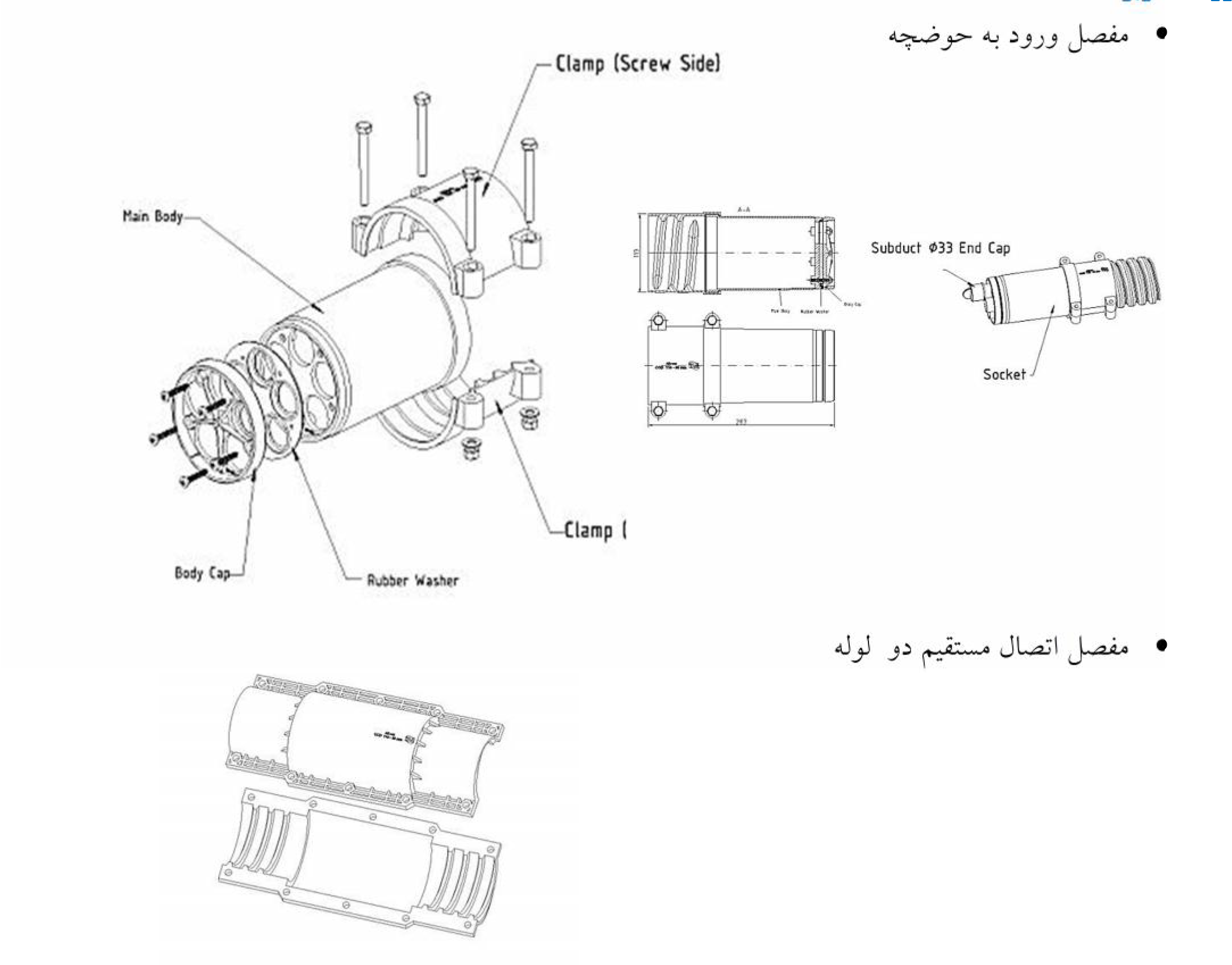
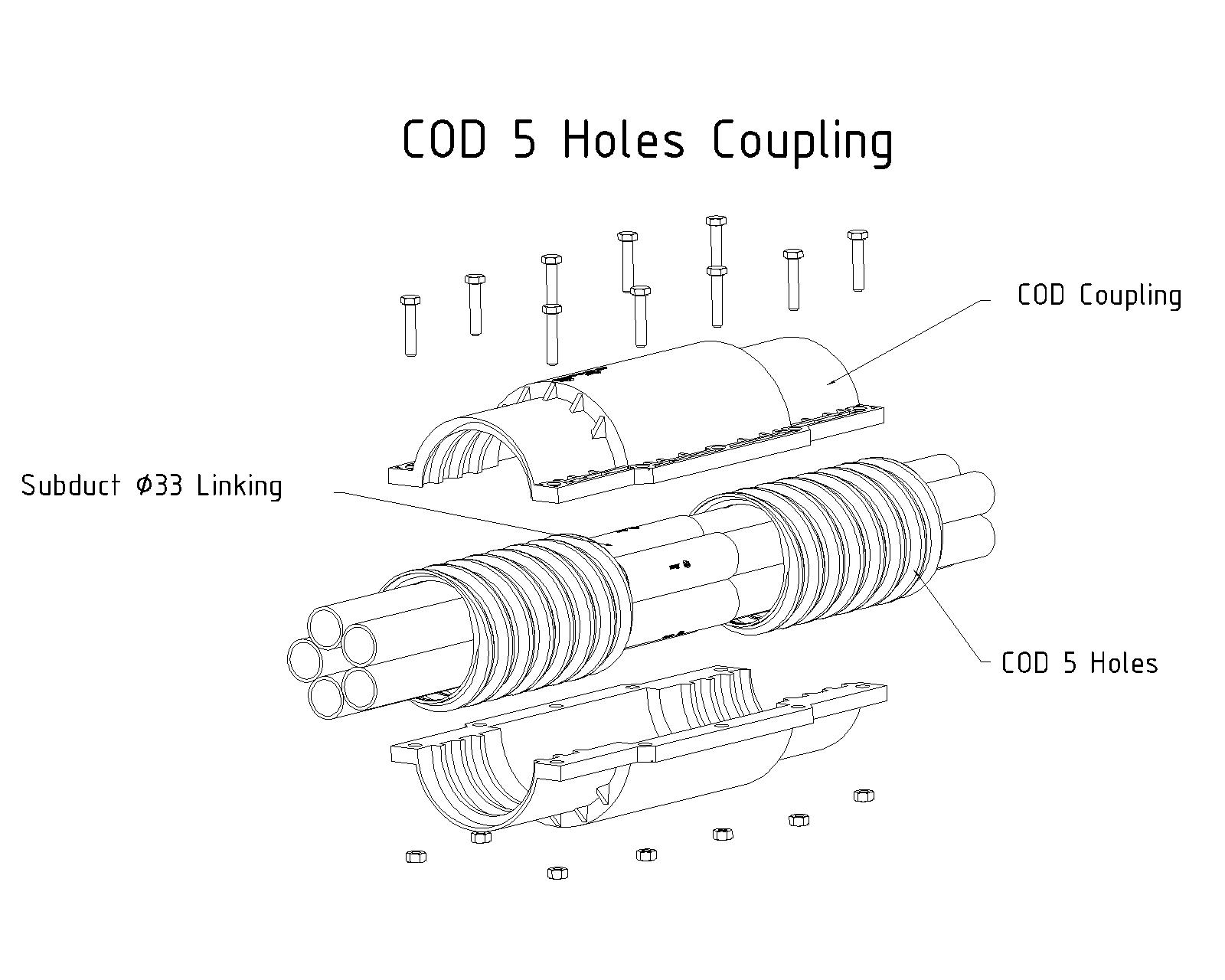
6. The 110 joint consists of two pieces. Therefore, the two bodies of the 110 joint, by means of a rubber gasket, protect the glass sleeve area and are connected and sealed with bolts and nuts—observing the threads formed on the COD pipe and the 110 joint. (according to Figure 16)
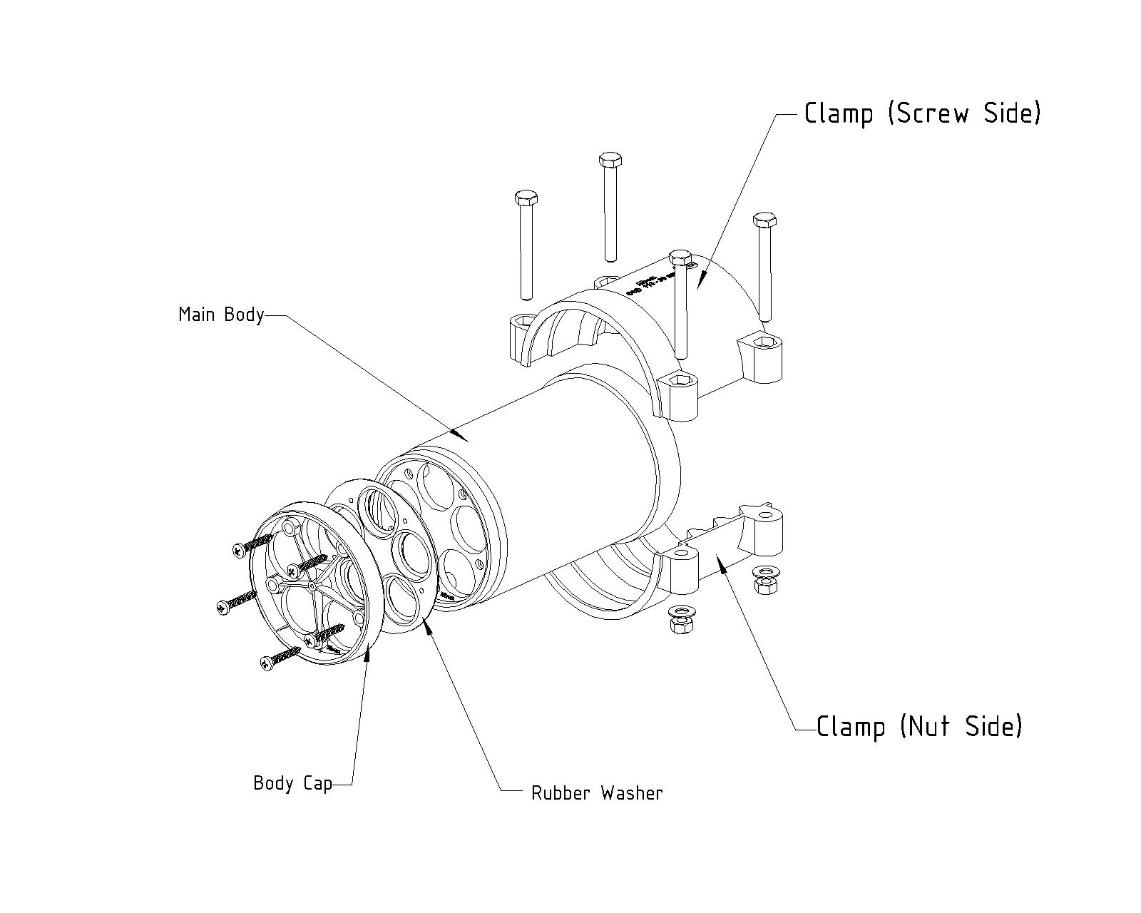
7. To connect the COD pipe to the inspection chamber or Type 2 manhole, a fitting called the manhole entry fitting (connector) is required. After installing the COD pipe inside the duct, the COD pipe cover is removed. The protrusions (fusion points of the subducts) are cleaned with a file, and then the installation steps of the connector are carried out as shown below. (Figure 17)
Note: The pipe length along the excavation route must be greater than the distance between the two manholes.
Method of Tapping (Branching) in COD Pipes:
- To tap from the main pipe installed inside the duct (any number) COD, a 45 × 110 joint can be used. The principle of using this type of 45 × 110 joint is similar to the connection between two COD pipes, with the difference that another pipe or subduct (as a third pipe) will branch from it. After the two 250-meter coils installed in the duct have had their covers removed by the cutter and the colored subducts have been connected to each other by glass sleeves after cleaning (filing the fusion points), any of the colored subducts can, as needed, be directed along the branch route according to the stated steps using a glass sleeve.
- The cut pipe (colored subduct) is capped in the 45 × 110 joint, and the selected branched subduct continues its route by connection to the sleeve. (according to Figure 18)
Use of Mechanical Protection:
In some cases during pipe laying, if the last row of pipes (considering the last hole of the manhole) has a laying height in the carriageway or sidewalk less than the elevation code announced in the execution instructions, mechanical protection shall be used. This protection includes pouring 10 centimeters of concrete with a grade of 200 over the last row of pipe laying.
It is evident that if the height of the last row of pipe laying is 30 centimeters, concrete with a grade of 250 or 300 shall be used, and furthermore, in other cases such as a weak duct bed / presence of effective chemicals / railway crossing / cable and riverbeds or qanats, necessary coordination with supervision and design units shall be made.
Backfilling, Soil Compaction, and Site Cleaning:
After backfilling (soft soil) over the last pipe, backfilling with 30% gradation (coarse debris larger than 10 centimeters) shall be carried out in moist layers by workers to a maximum layer height of 15 centimeters.
Over the stated route, compaction shall be done using a compactor in a back-and-forth manner (as specified in the referenced regulations and tests). After completing the above operations, proceed to clean the operation site 100%.
Proceed to clean the operation site 100%.
.


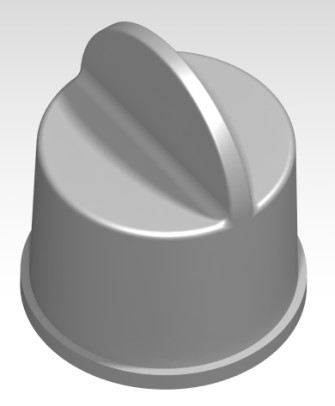
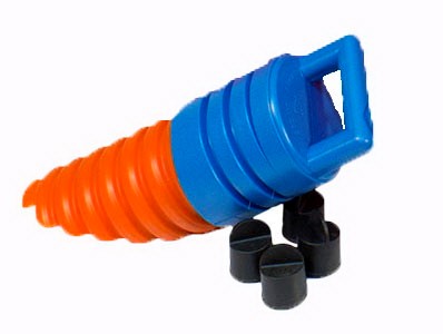 End cap for COD pipe:
1. Facilitates pipe laying in the soil: after trenching and at the start of the pipe-laying stage, this end cap can be used when pulling the pipe.
2. At the end of the work, it prevents insects, dust, foreign objects, and keeps the pipe clean for fiber installation.
End cap for COD pipe:
1. Facilitates pipe laying in the soil: after trenching and at the start of the pipe-laying stage, this end cap can be used when pulling the pipe.
2. At the end of the work, it prevents insects, dust, foreign objects, and keeps the pipe clean for fiber installation.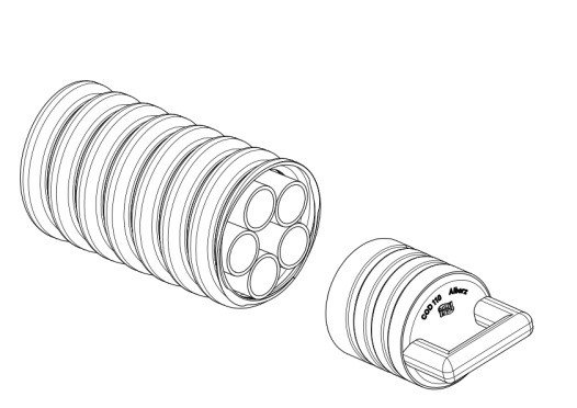
Reviews
There are no reviews yet.