

Fourth Generation of Telecommunication Pipes
The country’s telecommunication infrastructure, despite the wide copper network, faces many limitations in development and bandwidth. Due to the aging of the existing network, the country has incurred high costs for years in maintenance and expansion. Since the communications industry is developing worldwide, the demand for replacing a new generation of passive components as a secure platform for urban services with wide bandwidth has increasingly become the focus of clients. In this regard, Alborz Industrial Group (Alborz Pipe and Fittings Company) has introduced another generation of pipes under the brand name Micro Duct in its production portfolio. This product has been fully localized to meet the needs of engineers and clients. It is used for intra- and inter-city networks (FTTX, CCTV & IT).
Alborz Industrial Group has the capability to custom-produce the size and model of the required Micro Duct.

Micro Duct
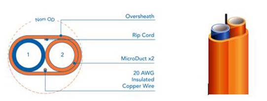
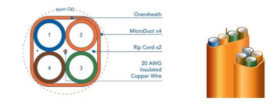
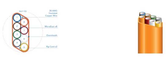
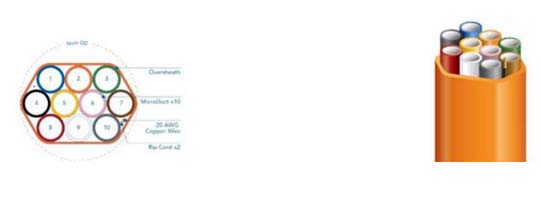
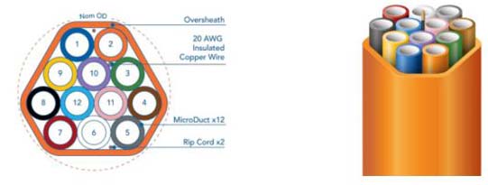
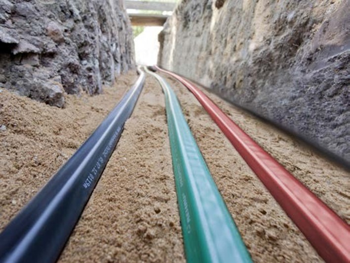
Micro ducts are the latest and most cost-effective solutions for fiber optic cable transfer (AIR BLOW) and are considered the fourth generation of telecommunication pipes. Micro ducts are essentially high-density polyethylene pipes, abbreviated as HDPE (High Density Polyethylene). They have one large outer pipe and several smaller inner pipes inside it. The inner chamber of the central pipes provides a pathway for fiber optic cables. Using non-biodegradable polyethylene and avoiding metallic structures allows micro ducts to be buried directly in the ground, creating an underground channel for fiber optic cables.
As you know, PE is a highly flexible chemical material, and producing micro ducts with polyethylene creates great mechanical resistance against pressure, torsion, bending, and impact, while also making it easier to bend around curves in the channel path.
In fact, micro ducts are sets of standard channels combined, consisting of two or more micro ducts placed under one sheath. As a new generation of transit channels for fiber optic cables, telecommunication cameras, and network transmission, they can vary in the number of channels and sizes depending on use and installation location. They can also be ordered in any color.
Micro ducts are produced in 1 to 12 channels and in lengths of 250, 500, 1000, and 2000 meters. The fiber optic cables used in micro ducts are known as AIR BLOW cables (air-blown fiber or micro fiber), and they are installed using the Air Blown Fiber (ABF) system.
Advantages of Micro Duct:
Flexibility in network design
Easy branching
Speed in network upgrading (fast cabling operations)
Ease of network maintenance
Cost-effectiveness in network transmission
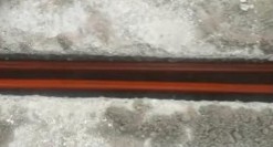
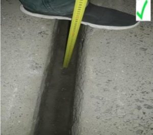
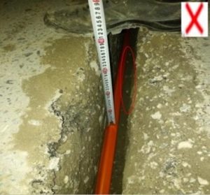
Minimal cost and space required for excavation and installation, especially flat micro ducts (~3 cm width)
High cable blowing distance
Wide variety in sizes, lengths, and colors
High strength against mechanical pressure
High strength against environmental factors
Easy identification of network lines in long paths via color codes
Easy injection into existing traditional telecom infrastructure (3- and 4-hole sub-ducts and ducts in manholes)
Ability to connect to third-generation O.D. pipe systems (Alborz Industrial Group product)
Reduced investment costs in projects
Updated standards for cabling and branching micro ducts
Production diversity in size, color, diameter, and model
3-channel micro duct


Different types of micro ducts:
Today, micro ducts are categorized based on the arrangement of micro tubes as follows:
Flat: In this type, the trench width can be less than other models (maximum 3 cm), resulting in significant reduction in project excavation and restoration.
Triangular
Quadrangular
Hexagonal
Some models of micro ducts can be installed in old telecommunication infrastructures (sub-ducts, PVC pipes, and polyethylene pipes). In this method, the size of the old base is determined, and the proper micro duct is selected for installation, allowing the existing infrastructure to be expanded several times using micro ducts.
Production of micro ducts with anti-UV materials:
Micro ducts can also be produced with anti-UV materials for protection in open storage environments. This option is available upon request.
Production of micro ducts with Rip Core:
A polyester thread placed in the outer sheath of the micro duct to create a slit for stripping.
This option can be added or removed upon request.
Production of micro ducts with Copper Wire:
A copper wire is embedded along the micro duct, allowing precise detection of the path using a metal detector after project execution and surface asphalting. In case the wire is cut at a point in the fiber path, the exact location of the break can be identified by devices such as Dynatel.
This option can be added or removed upon request.
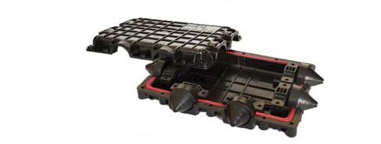
Micro duct and micro tube joints – I, Y, T, H joints:
As with various cables, pipes, and telecommunication joints, different joints have been designed and manufactured for micro ducts. They vary according to their type and outer diameter. The distinction of micro duct joints is their ability to branch, which is why a variety of joints (I, Y, T, H) are designed and produced for them, each serving a specific purpose in telecommunication designs.

Straight joint (I)
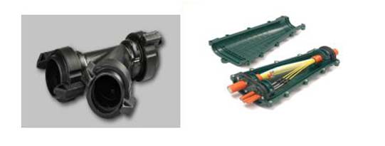
Branch joint (Y)

Branch joint (T)
Branch joint (H)
Straight Connector
Connectors are also provided for connecting the internal tubes of the micro duct, which differ depending on the size and type of tube, and are called straight connectors.
End cap
The end cap is another connection for internal micro duct tubes, used to seal empty tubes. It prevents dust, water, and insects from entering, ensuring long-term protection of unused micro tubes.
Gas block
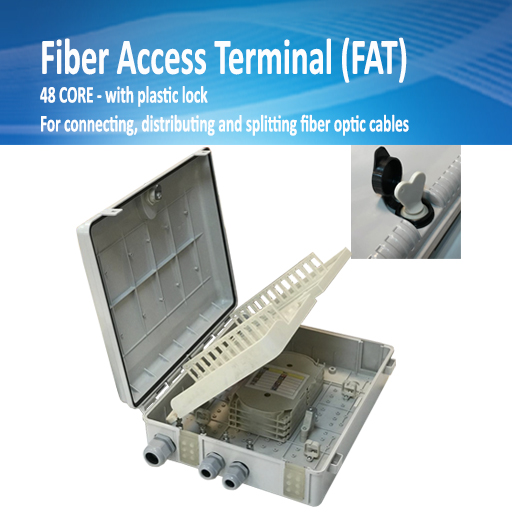
At the end of installation and after inserting the fiber, a gas block is used to hold and secure the micro tube inside the FAT.
Cables used in micro ducts (types of micro fibers):
Air-blowing cables, also known as macro fibers, are suitable for use inside micro ducts. Despite being smaller in size compared to underground and channel cables, the data transmission capacity of micro cables is equal to those mentioned. Due to their physical characteristics and ability to be placed inside micro ducts, these cables are used in all communication and telecommunication projects. A specific type of this category has rodent-resistant properties. Micro cables are also used in FTTH (Fiber to the Home) projects in the access domain.
These products are categorized as follows:
Multi-tube micro fiber: In this category, each loose tube contains 12 to 24 cores, and each micro fiber optic cable has between 12 and 288 cores.
Single-tube micro fiber (Central Tube): This type of micro cable contains 2 to 24 cores.
Micro duct and micro fiber optic cable
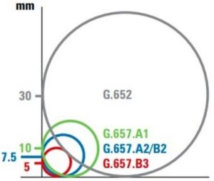
The term “micro fiber optic cable and micro duct” refers to a new type of fiber optic cable used in FTTH projects. These are high-capacity, small-diameter cables. Bend Insensitive (BI) fibers allow for higher density of fibers inside micro ducts, as BI fibers are less sensitive to bending compared to standard optical fibers.
BI fibers can have smaller primary buffer coatings, 200 microns or less, compared to the usual 250 microns of standard fibers. This allows more fibers to be packed into less space.
Important notes when using micro ducts:
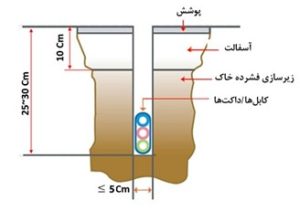
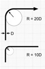
For ducts with a diameter less than 5 cm, the minimum bending radius must be 20 times the tube diameter, and for ducts larger than 5 cm, 20 times the inner diameter.
At maximum capacity, only 50% should be used under ideal conditions and up to 70% at most. As this number increases from 50% toward 70%, the continuous shooting length of the micro fiber decreases.
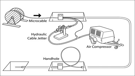
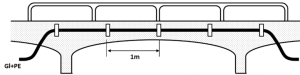
The fiber shooting process is a highly precise and specialized operation in which compressed air from powerful compressors and a Micro Fiber Blower is used to blow the fiber inside micro ducts, enabling fiber cabling over distances exceeding 1 km.
It is essential that the equipment used in the fiber blowing device supports the size of the optical fiber cable; otherwise, the cable will bulge and slip, reducing efficiency. The quality of the micro ducts also directly affects performance.
In this technology, air reduces friction between the micro fiber cable surface and the inner wall of the micro duct. Two types of friction must be overcome:
Static friction: the force required to initiate movement of an object.
Dynamic friction: the force acting when the object is already moving, which determines how much effort is needed to keep the fiber from contacting the duct walls.
The heavier the cable (higher core count), the greater the friction, and thus more force and air pressure are required. Lubricants such as air help minimize friction.
When designing fiber cabling, future requirements must be considered, including fiber type, number of cores, and spare cores for redundancy.
Old vs. new systems – Using micro ducts for smart buildings:
In modern buildings, micro ducts can replace copper cables (network, coaxial, intercom, etc.), enabling fiber optic infrastructure for smart buildings.

Execution notes:
The micro duct path should not exceed two 90° bends or one 180° bend without a Pull Box.
For ducts <5 cm diameter: minimum bend radius = 6 × inner diameter.
For ducts >5 cm diameter: minimum bend radius = 10 × inner diameter.
Twisting of ducts is not acceptable.
Without Air Blown Fiber, pulling force depends on duct length, sheath material, and number of bends.
Prefer straight paths with Pull Boxes.
At aggregation points, ducts should be 2.5–7.5 cm above the floor.
Seal all empty ducts with end caps.
Number of branches to be defined per order.
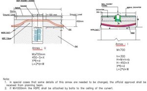
Concrete filling may be single-stage or two-stage.
List of Completed Micro Duct Projects
| Project Name | Micro Duct Type | Year | |
| 1 | Shahrekord Municipality | 7-channel | 2016 |
| 2 | IT Organization of Karaj Municipality | 7-channel | 2016 |
| 3 | FANAP | 7-channel | 2016 |
| 4 | Fars Telecommunication Company | 7-channel | 2016 |
| 5 | Isfahan Industrial Town | 7-channel | 2017 |
| 6 | Saba Net (Residential Town in Bushehr) | 4-channel | 2017 |
| 7 | Gilan Industrial Town | 7-channel | 2017 |
| 4-channel |


Reviews
There are no reviews yet.